 If your studio is haunted by things that go hum in the night, pay closer attention to the principles of grounding.
By Neal Brighton and Steve Oppenheimer
Even the most talented recordist must plan carefully in order to survive the vagaries of fickle fate. An alarm system and a good insurance policy protect your studio against thieves and natural disasters. Secure (and perhaps a bit smug) in the knowledge that your guard is up, you may be quite literally shocked to discover that your projects, your precious gear, and perhaps your life could be at serious risk from a dreaded disease: bad grounding.
Most studio professionals have an encyclopedic collection of horror stories about the wages of electrical sin. At best, improper grounding causes unholy noise in the audio system, immediately labeling your recordings as amateurish or even unlistenable. Often, sensitive equipment displays mysterious behavior and requires unexpected pilgrimages to the repair shop. In the worst case, poor grounding could lead to electrocution or fire. Fortunately, the problem can be cured if you diagnose it in time and treat it promptly.
A properly wired and grounded system starts with the AC lines. But you also must consider your audio cables, whether your lines are balanced or unbalanced, what type of connectors or adapters you’ve used, and so on. We have a lot of ground to cover, so we’ve divided the discussion into two parts. In Part 1, we’ll review the potentially hair-raising fundamentals of AC grounding, including both house and equipment-chassis grounding. Part 2 will examine sane wiring schemes and rack-mounting strategies and establish a troubleshooting procedure for minimizing sonic mayhem.
One Leg To Stand On
It’s important to determine whether you have a clean power source. You must know if there is anything else drawing power from the same AC circuit as your equipment.
If you don’t already know which circuit breakers control which outlets and lights in your building, take a few minutes to find out. Get a few radios or lamps, plug them into every wall socket in the house (including the outlets where your equipment is plugged in), and turn them on. (Make sure your computer and music gear are turned off.) Find the breaker panel, throw the breaker for each circuit, and see what stays on and what goes out. Write down which outlets and lights are controlled by each breaker.
The best news would be that your equipment is the only thing on its circuit. The worst news would be that half the house is on the same small circuit you want to use for the studio gear. (This is more common in older houses and apartment buildings.) If you have bad luck, you must find out if there still is enough power on that circuit to power the equipment you want to run and identify any electrical devices that might cause equipment problems.
Troublesome devices include any appliance with an electric motor that turns on and off. Refrigerators, dishwashers, clothes washers and dryers, trash compactors, and microwaves are common culprits. Fluorescent lights and cheap dimmer packs also should not share a circuit with audio gear. These devices cause power fluctuations, hums, clicks, and pops when you least expect them.
The Right Stuff
Whether you are assembling a new studio, or trying to debug an existing system, one of your first tasks is to determine if you are drawing too much power from the circuit to which your equipment is connected.
Calculating the power consumption of your equipment is easy; most manufacturers give you this information on the back plate of the equipment or in the technical section of the manual. However, while equipment is rated in terms of power requirements (watts), circuit breakers arc rated in terms of current (amperes). Because the voltage is more or less constant at 117 VAC, current and power are directly proportional, which leads people to use them interchangeably.
You can use the equation Current = Power/Voltage (I = P/V, derived from Ohm’s Law; see the sidebar on p. 74 in April 1990 EM) to figure the electrical current required by each piece of equipment. Keep in mind that the output power of your amp doesn’t correlate to the amount of current it draws; use the electrical-power requirement of the amp in your calculations.
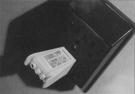
FIG. 1: Three-prong AC-outlet analyzers reveal whether an outlet’s hot, neutral, and ground terminals are disconnected, or the hot terminal is reverse-wired with either neutral or ground.
Add up the current requirements for all gear on the circuit and compare the total with the maximum current rating indicated on the circuit breaker (see the sidebar “Power to the People”). If the total current requirement exceeds the current rating of the circuit, the system is unsafe, and the breaker will repeatedly kick out.
One nice thing about electronic music equipment is that most of it doesn’t require much power. Your mixer, tape deck, and power amps consume most of the power, but even so an average home studio should run easily on one 20-amp circuit, as long as there is nothing else on the circuit. This is a good thing, because you can run into major problems (such as out-of-phase wiring or widely separated ground potentials) when you use more than one circuit. So make life simple by keeping all studio gear on the same circuit.
Checking the House Ground
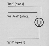
FIG. 2a: In a properly wired AC outlet, all three conductors are connected, and the color code is observed.
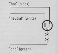
FIG. 2b: Disconnecting the ground wire creates a potential shock hazard and defeats surge and spike protection.
In newer houses, modern electrical codes usually guarantee a good ground, but this may not be the case in older houses and apartments. The best way to quickly test your outlets is to use a 3-prong AC outlet analyzer (available from Radio Shack and most other electronics stores; see Fig. 1), which indicates whether the AC hot wire’s polarity is reversed or the neutral (left prong) or ground (third prong) is disconnected.
Be aware that the third prong isn’t necessarily connected to anything (see Fig. 2). Don’t make foolish assumptions; test the circuit. If you find a problem, call the electrician; it’s cheaper than a fire or a hospital bill.
If you only have 2-conductor outlets, you can use a neon circuit-tester (also available from Radio Shack and most other electronics stores; see Fig. 3) to test the ground. Put one end of the circuit tester on the metal screw that secures the cover plate of the outlet, making sure there is no paint on the screw head. (Paint is an insulator.) Put the other in the socket itself (in the small slot of a polarized plug). If the tester glows, you have a good ground.
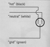
FIG. 2c: Sometimes an outlet’s polarity (i.e., the neutral and hot connections) is reversed, which creates a shock hazard and can cause noise.
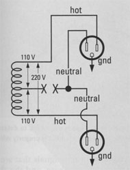
FIG. 2d: In this duplex outlet, the neutral lead is not connected. The voltage could vary unpredictably from 0 to 220 VAC, creating a shock hazard and possibly damaging equipment.
WARNING
It is most important to keep in mind that when it comes to AC wiring, government and insurance underwriters’ electrical codes take precedence over anything suggested here. These rules and regulations, which vary in different regions, are designed for safety, and safety always comes first. If you are unsure of what you’re doing, call a professional electrician.
In some studios, the ground of the circuit powering the equipment is isolated from the rest of the building’s circuits. As a result, all the outlets on the studio circuit are grounded separately from all other circuits in the house. This is accomplished by disconnecting the ground for the studio circuit from the grounding strip in the breaker box and wiring a separate, true earth ground. The electrician must install special colored outlets to accommodate this type of circuit. Each special outlet is connected to the separate ground by an additional wire in the wall conduits.
Isolated grounding can help eliminate ground-based noise by isolating the studio gear from other sources of noisy ground currents, such its large appliances. However, this noise reduction is predictable only in equipment with balanced audio connections. If you are building a professional-level studio from the ground up (so to speak), establishing an isolated ground might be the first thing to do. However, it usually is a last resort in an existing facility.
Chassis Ground
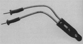
FIG. 3: Neon circuit testers use a neon bulb to determine whether an outlet or piece of equipment is properly wired.
In a well-designed audio system, the chassis ground (negative terminals) of the power supplies are connected together and all audio-cable shields are connected together (signal ground). Somewhere along the way, these two grounding systems should be connected together as well. (If all your gear is properly designed, these grounds will already be connected for you, but don’t bet on it.) The resulting system ground point is the zero signal reference potential. The whole system is connected to the building’s ground, which ideally is at the same potential as the earth (earth ground).
On most electrical equipment, the metal chassis should be connected to the safety ground line through the third prong of the power cable, but sometimes the safety ground comes loose. One quick way to verify this connection is to use an ohmmeter to check the continuity between the third prong of the AC plug and the metal case of the equipment. (Make sure to test a part of the case that is not painted.)
It’s important to make sure that safety grounds are connected, as they protect you in the event of a short circuit between the chassis and the hot line. Should a short circuit occur inside the equipment, the current will pass through the safety ground to earth, and not through whoever touches the equipment. (Remember, electrons always take the easiest path to ground.) This need for a safety ground also is a strong argument against the use of 3-prong-to-2-prong AC ground lifters (a.k.a. AC plug adapters), which defeat the third-prong safety ground.
If you have older gear with 2-conductor AC connectors, you could have a shock hazard between the chassis of the device and the chassis of, say, a mic. (Newer UL-approved, 2-conductor gear should be okay, but take precautions anyway.) A microphone case is grounded through the cable shield to the mixer or preamp, so if the latter is properly grounded, the mic should be safe. However, if an older device such as a tube-based guitar amp or a powered mixer uses a poorly grounded, 2-conductor power cord, you might become the easiest path to ground, which could give you a hot time in the old town. Microphones with properly wired, balanced XLR connectors don’t pose much of a problem, as the two main conductors carry signals that are 180 degrees out of phase, and the shield does not carry a signal.
To test the ground connection of a mic, use a neon circuit-tester (see Fig. 3) or high-impedance AC voltmeter, and without touching both chassis at the same time with your body, place one lead on the amp or mixer chassis in question and the other lead on the mic chassis. (For added safety, use a clip to attach a lead to the amp chassis, instead of hand-holding the lead. Put one hand in your pocket so your arm can’t become a path to ground.) If you find even a few volts difference, you could have a serious problem. First, try reversing the amp’s AC plug in the outlet, or if the amp has a ground-reverse switch, try flipping that. If these remedies don’t work, try plugging the amp into a different outlet on the same circuit. If nothing helps, don’t use the amp; any alternative beats electrocution.
A Great Leap Forward
Well, that about covers the fundamentals of your electrical system. If you have tested your outlets and, with help from your friendly local electrician, corrected any faulty conditions, your studio has come a giant leap closer to electrical sanity. Next month, we’ll turn our attention to discovering and correcting ground loops and other wiring conditions that make your studio gear hum and your ears burn.
Power To The People
By Steve Oppenheimer
Regardless of where your local electric company gets its juice, the AC power reaches your house by way of two 117-volt hot wires (at a frequency of 60 Hz, +/-001%), each carrying a signal that is 180 degrees out of phase with the other. In reality, the AC signal fluctuates above and below 117 volts, depending on the demand for electricity on your local network at any point during the day.
You also have a neutral wire and a ground wire. The neutral wire is grounded to earth at the local utility pole’s step-down transformer. At the service point where the power line enters the house, the neutral wire is grounded again.
The ground wire is a conductor brought in from the service point to provide a safety ground for the chassis of anything plugged into the outlet. It normally is connected to the building’s cold-water system, assuming you have copper water pipes and not plastic. If the entire house has plastic pipes, a six-foot copper rod may be driven into the ground to create a true earth ground. The ground wire normally is at the same potential as the neutral, but not always. There is sometimes a current in the neutral wire, which is why it should never be connected to the ground wire.
All the wires meet in a metal box with fuses or circuit breakers. From this box, the power is divided into two main strips, or legs, which run down the left and right side of the box. Each leg consists of one 117 VAC hot line that shares a common neutral wire. Each of these legs is then divided into 15-, 20-, or 25-amp circuits that run to different parts of the house. At the bottom of the breaker box, you usually find a strip that connects all the grounds from the different circuits to the main ground wire.
For heavy-duty appliances such as an electric stove, both hot legs are used to create a 240-volt line. In industrial areas, several different three-phase wiring schemes are commonly used, including both 240-volt and 480-volt systems. Some systems also provide 208 VAC and 277 VAC legs for motors and fluorescent lights. If you plan on hooking into these systems, you should have a qualified electrician do it for you.
Most modern electrical boxes have circuit breakers rather than fuses. The circuit breakers are designed to protect the electrical system from overloads. If the current drawn from a circuit exceeds the maximum value of the breaker, the breaker trips and shuts down the power to that circuit. This safety feature prevents the circuit from overheating and causing damage to equipment, or even starting a fire.
In a properly wired, polarized 2-prong outlet, the left (long) prong is neutral, the right is hot, and the mounting screw is ground. In a 3-prong outlet, the third (cylindrical) prong is ground. The wiring in buildings varies depending on local building codes, but most conform to a more or less universal color code for the different wires. Normally, white is used for the neutral, ground is green, and hot is anything but white or green, with black being the most widely used color.
If you recognize this scheme as being similar to unbalanced audio connections, go to the head of the class. In both cases, a hot signal in one conductor is accompanied by a neutral signal in the other conductor. In balanced connections, two hot signals that are 180 degrees out of phase with each other are carried in two conductors while the neutral signal is carried in a third conductor. This eliminates any noise induced by external electromagnetic radiation from devices such as electric guitars, which appears in all conductors at the same phase. In England, the AC power system is balanced, which is why British studios are generally more hum-free than their American counterparts. Unfortunately, American electrical codes do not provide for balanced AC power lines.
On Solid Ground, Part 2
Don’t let a humming sound system sing backup on your hit-to-be.
 A friend of ours recently decided to put together his own recording studio. He spent hours talking to salespeople at the local pro audio store and left with about 30 boxes of equipment. When he set up his studio, he didn’t even bother to read the manuals. After all, the salesman had already told him everything he needed to know to get started. He took an old equipment rack and threw most of his outboard equipment into it. Next, he put the mixer and tape deck up on an old table, connected his audio lines with a bunch of guitar cords, wired up his speakers and power amp, and plugged the AC into whatever outlets he could find. Then he said, “This is it, I’m ready to make music!” Not!
Sure, he was able to turn on his keyboards and drum machine and get a sound, but the sound that came out of his speakers was like no patch he had ever heard before. He had the hum from hell, and it was coming from every piece of equipment he turned on. At first, he thought that crook of a salesman sold him a bunch of cheap gear. Unfortunately, our friend didn’t realize that any piece of gear sounds like garbage if it’s improperly and poorly grounded.
Ground Loops
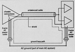
FIG. 1a: The devices in the studio are grounded through the cable shield, the chassis, and the AC ground, which can form a ground loop.
In last month’s issue (see “On Solid Ground, part 1”), we discussed the fundamentals of house AC wiring and the principles of safe grounding. If you missed Part 1,go back and read it now. The issues covered this month are of secondary importance if your AC outlets are unsafe.
Having established a safe electrical-system ground, turn your attention to preventing ground loops. A ground loop is formed when equipment is connected to ground through more than one path (see Fig. 1).
The situation is complicated by the fact that op-amp inputs, bypass capacitors, and other internal components connect to ground by way of the equipment chassis. In poorly designed gear, internal ground loops can occur. If an unwanted signal (RFI, noise, etc.) gets into the ground line, especially in preamps and other high-gain circuits, it could get into the audio path as well. Then it travels between components, gets amplified, and makes your trained ears extremely unhappy. Sometimes there’s nothing you can do about this situation short of having a professional redesign the device’s internal grounding or not using the equipment at all.
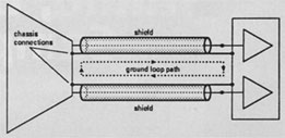
FIG. 1b: When a stereo device feeds a mixer through unbalanced lines, another ground loop can be formed.
Once a ground loop forms, it acts as an antenna, aggravating the situation by picking up radio-frequency interference (RFI) and electromagnetic interference (EMI) from nearby strong AC fields. Ideally, an audio-cable shield doesn’t carry signals, but in real-world situations, signals flow through the shield. This creates lines of force that can be induced into the hot lead of other cables, causing noise.
Rack-Mounting
If you have your equipment on a tabletop, I strongly recommend you spend a little money and buy or build a rack. You spent some bucks for all that equipment, and you should protect your investment.
Make sure all unbalanced equipment is isolated in the rack. If you have both balanced and unbalanced equipment, try to keep them in separate racks, or face the possibility of unavoidable ground loops. You don’t want the metal housing from each piece of rack-mounted gear to touch its neighbor and cause a ground loop, so if you are using a wooden rack, make sure you leave a bit of space between each piece of equipment.
Rack-mount gear also can find a path to ground through the rack’s metal mounting rails. The most common insulation method is to use nylon washers on the front and back of the gear’s rack ears. You also can run some electrical tape down the rails. Even then, rack screws can touch the rack where they go through the holes, especially since the insulating paint scrapes off the screws with repeated use.
The solution is to use nylon washers in the form of collars that go inside the screw holes. (These washers often are used for mounting voltage regulators to heat sinks.) Check your local electronics and industrial hardware supply stores. You also can use nylon mounting bolts to secure lightweight equipment that won’t be moved. However, nylon bolts aren’t very strong, so don’t use them for touring racks or heavy gear such as power amps.
Once your equipment is in the rack, turn it around and look at the back. See that bunch of AC cords just hanging there? They are bad news when you start plugging in audio cables. AC power cords emit electromagnetic fields that can cause EMI in audio cables.
FIG. 2: A properly wired rack.
The best way to get around this problem is to clean up your wiring act. Your friend in this endeavor is the cable tie, which can be bought at any electronic-parts supply house. (If you rewire your gear often make sure to get reusable cable ties or use regular plastic garbage-bag ties.) Run all power cords down one side of the rack, tying them together as you go, and terminate them at a rack-mount power conditioner or a power strip bolted to the rack’s left rear side. (Most standard AC cables connect on the equipment’s left side as you face the rear, but there are exceptions, as shown in Fig. 2.)
Bunch the AC cables; do not bundle them into a loop. Run your audio cables along the opposite side. If you have an open-frame rack, don’t wrap the cables around the support poles or you will create an electromagnet. Beware of external “wall-wart” power supplies, as they are a major source of EMI. If these external supplies convert to DC, keep them away from AC cables, treating them like audio cables.
If all your equipment is plugged into the same grounded circuit, you reduce the possibility of ground loops. But if different parts of your rack are plugged into different circuits with different grounds, you will encounter problems when you connect their audio signals through the patch bay or mixer bus. This is particularly important if you are trying to use two pieces of equipment that are in different rooms with different AC outlets.
When all this careful wiring is done, you should have one power cord coming out of your rack and no mess. You should have AC power running down one side of your rack and audio cables down the other (see Fig. 2). Keep speaker cables away from both audio and AC cables. MIDI cables can emit RFI, as well, so keep them away from audio lines. If necessary, you usually can get away with running AC and MIDI cables together.
Also remember that anything with a power transformer radiates a magnetic field that can cut right through the shielding of your audio cables, so make sure your power amp and the power supply for your mixer are at least a few feet away from your equipment. The magnetic fields drop off exponentially, so even a little distance between cable runs can help a lot.
Audio Cables
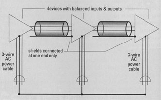
FIG. 3a: In a telescoping shield, the audio shield is disconnected at one end of the balanced-line cable.
Aside from the chassis ground path, electrons can go to ground through audio cables. You can take several steps to avoid ground loops here.
If your studio is a -10 dBV unbalanced system (usually RCA and 1/4-inch phone plugs), keep the entire studio that way. Don’t try to wire one or two pieces of equipment with balanced lines. Keep your mixer, outboard gear, and tape deck physically close together so cable runs are as short as possible. In some cases, the best you can do with an unbalanced system is bundle the audio cables close together to reduce the area of an unavoidable ground loop, which minimizes the ground loop’s potential to act as an antenna.
In a balanced-line system, the shield doesn’t carry the audio signal. One way to stop a ground loop in a balanced system is to cut the shield at one end of an audio cable, eliminating one path to ground. This is called a telescoping shield (see Fig. 3a). This cannot be done with a single-conductor, shielded, unbalanced-line system. However, if your system is unbalanced but your cable has two conductors plus the shield, connect one conductor to positive and one to negative at both ends and the shield to negative at one end. If a device has a ground-lift switch or removable link in the terminal strip that disconnects the signal ground from the chassis ground, use that instead of cutting the shield (see Fig. 3b).
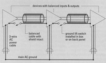
FIG. 3b: A ground-loop switch makes it easy to implement a telescoping shield.
MIDI cables also have a ground line (pin 2, which is the middle pin), so when you connect them to different boxes, it is possible to create a ground loop. If your equipment is wired according to the MIDI specification, this shouldn’t happen, but it is possible and should be kept in mind when debugging your studio.
Cable Quality
The quality of your audio cables can make a big difference in how your studio sounds. Beware of cables with poor or no shielding. Whether your studio uses +4 dBm balanced lines or -10 dBV unbalanced lines, all cables should be properly shielded.
If a cable has a poor shield, it allows EMI to enter the cable conductors. This interference usually manifests itself as a buzz and can be quite loud. There are three common types of shielding: braided, stranded, and foil.
The general principle is the same for all three types of shielding: the more physical coverage there is, the better the shield.
Wires that need flexibility, such as guitar or microphone cables, usually have a braided shield. Cables that aren’t moved much have a foil shield, which provides superior coverage. Stranded shields (containing individual unbraided wire strands) generally provide the least coverage.
All braided shields aren’t created equal; the coverage depends on how tight the braid is. The cable spec specifies the percentage of shield coverage, which correlates to physical coverage; tighter braid is better. Cheap guitar cords often use loosely braided (and sometimes stranded) shields that provide as little as 70 percent coverage. Don’t wire your studio with cables of this type.
Some cables with plastic-coated plugs on the end do not run their shields under the plastic. Metal plugs are better because you know the shield is complete from one end to the other. If you must use any kind of adapter, make sure it is all metal.
Line Conditioners
Once you have worked out the grounding situation, spend a little money making sure your AC power is friendly to your musical equipment. AC power tends to carry electrical junk along with it (such as RFI and EMI), so it’s important to have some filtering on your power strip. Clean, consistent AC power helps protect and lengthen the life of your equipment and reduces noise.
A good, inexpensive start in the war on RFI is to put ferrite beads around the AC power cables coming out of the duplex wall outlet and around audio cables where they enter the preamp. But AC line conditioners are a more complete solution. (Try both methods together.) Many brands and designs exist, but a good line conditioner should have surge and spike protection, RFI filtering, and EMI filtering. The surge and spike protectors, of course, protect your equipment from power transients and surges.
Keep in mind that not all people have RFI problems, as these problems are random and vary depending on your location. But it’s a good idea to protect your equipment from as many possible problems as you can. Rack-mounted protection units are especially convenient, as they provide enough AC outlets to power the whole rack.
Line regulators are a big step beyond surge and spike protection. These devices smooth out voltage drops and surges and supply a clean, steady 117 VAC. (For a detailed explanation of surge and spike protection, RFI and EMI filtering, uninterruptible power supplies, and line regulators, see “Getting Wired: A Power Primer” in the April 1990 issue of EM.) [Note: also see “Power Hitters” on this Web site.]
Troubleshooting
Now that you know some basics about reducing ground loops, RFI, EMI, and hum, here is a troubleshooting procedure to weed out the worst offenders. Start by rechecking the AC, then check the racks, applying the mounting criteria and techniques we’ve presented. Next, unplug everything connected to the mixer except the power amp and speakers.
Since the mixer is the center of your audio system, it should be the central point of our studio grounding system as well; start analyzing the system there. Turn on the mixer and power amp and run the master fader up to see how much noise is in the monitoring system. If you have noise problems, it is possible (though unlikely) you have a loop between the mixer and power amp. Sometimes this doesn’t show up until you plug a signal into the mixer.
With a signal in the mixer, try unplugging the mixer from the amp and monitoring on headphones. If the hum is still there, the problem isn’t between the amp and mixer, so you should go back and make sure your audio cables are of good quality and are placed well away from other types of cables.
Once you’re satisfied that the mixer and amp are clean, start plugging the cleaned-up racks into the board or patch bay, one piece of equipment at a time, checking to see if the noise level goes up significantly with each piece of equipment. If it does, check the audio cable, replacing it with one you know to be of good quality. If the cable runs through a patch bay, bypass the patch bay and go straight into the mixer. This tells you if there is it ground loop in the patch bay. In a well-designed patch bay, audio grounds should be isolated from the patch-bay chassis, so any ground loops probably are in the audio chain, not the chassis. Still, it’s good to test for continuity between an unused patch bay jack and the chassis.
If you still have problems, change the polarity on the AC plugs. Go through the whole recording system and check every audio line for hum and noise.
If all else fails, and you still have ground loops in the audio lines, you may have to use audio isolation transformers on each of the offending lines. Although you can spend some serious money on high-end audio isolation transformers, you might get by with inexpensive Radio Shack models. However, sometimes these devices can add distortion and pick up RFI, so if they’re not really necessary, you’re better off without them.
The easiest way to find bugs in your recording system is to do a mix. When you are mixing, you probably use every bit of gear you have. In addition, your gear probably will be plugged in through the patch bay in many strange ways, so doing a mix also is a great way to check for ground loops.
Murphy Lives
Murphy’s Law runs rampant when it comes to grounding; anything that can go wrong probably will. Grounding problems can come from some of the strangest places. On a recent live video shoot, for example, the multitrack recording equipment was fine until the video people plugged into the AC power. Ground loops were running through the cameras, causing the equipment to experience major 60 Hz hum. There was an easy solution to this problem, though: get them off the AC circuit.
Most grounding problems can be dealt with easily using the techniques presented here and a little common sense. The latter, fueled by a healthy dose of caution, is the most important factor. Plan all parts of the system in advance, keep things neat, put safety first, and know when to call for professional help. Do it right, and the only humming you’ll hear will come from the singers.
Neal Brighton is an independent producer/engineer and co-owner of Sound and Vision studios in San Francisco. A Buddhist seer once told EM managing editor Steve O that his purpose in this incarnation was to learn about power. He never understood until now.
(The authors would like to thank Alan Gary Campbell, Chris Meyer, Kevin Kaiser, Larry the O, and Charlie Bolois.)